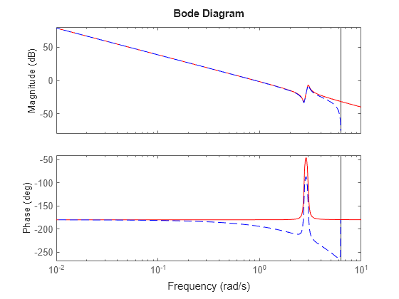

īode was faced with the problem of designing stable amplifiers with feedback for use in telephone networks.

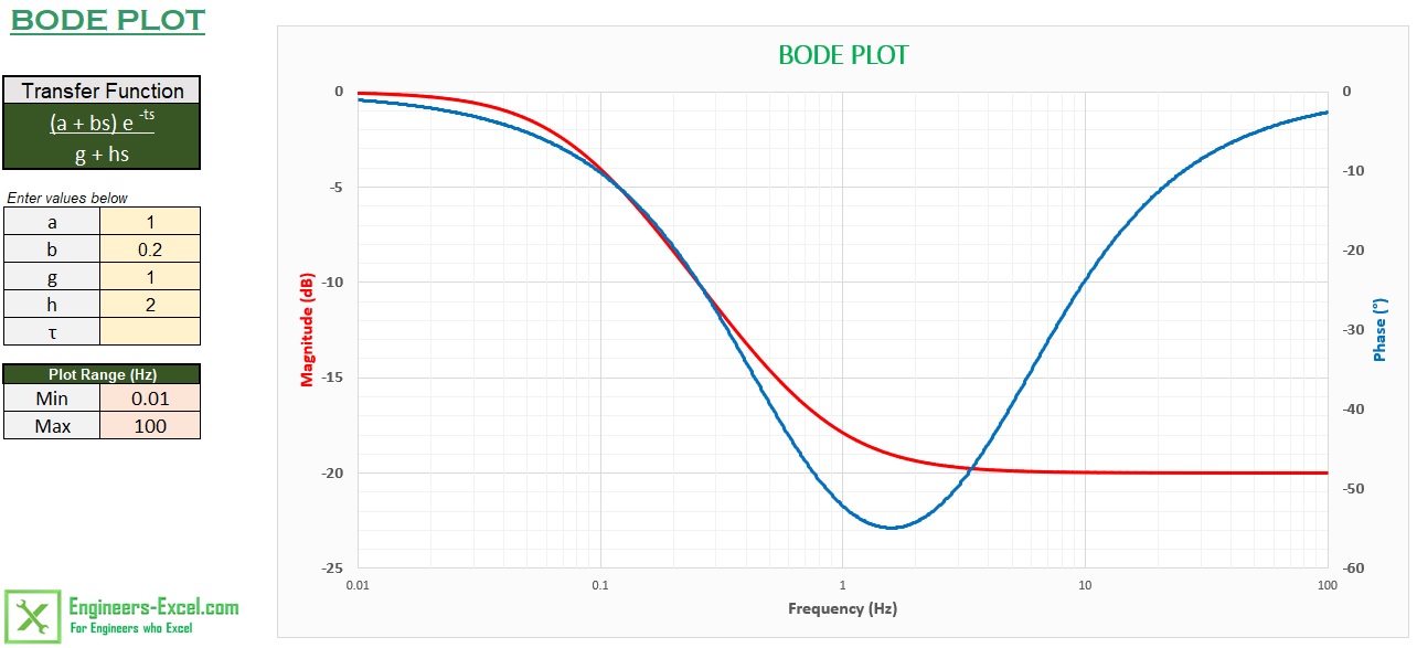
"Bode" is often pronounced / ˈ b oʊ d i/ BOH-dee although the Dutch pronunciation is Bo-duh. These bear his name, Bode gain plot and Bode phase plot. Overview Īmong his several important contributions to circuit theory and control theory, engineer Hendrik Wade Bode, while working at Bell Labs in the 1930s, devised a simple but accurate method for graphing gain and phase-shift plots. It is usually a combination of a Bode magnitude plot, expressing the magnitude (usually in decibels) of the frequency response, and a Bode phase plot, expressing the phase shift.Īs originally conceived by Hendrik Wade Bode in the 1930s, the plot is an asymptotic approximation of the frequency response, using straight line segments. In electrical engineering and control theory, a Bode plot / ˈ b oʊ d i/ is a graph of the frequency response of a system. Figure 1B: The Bode plot for a first-order (one-pole) lowpass filter the straight-line approximations are labeled "Bode pole" phase is 90° lower than for Figure 1A because the phase contribution of the numerator is 0° at all frequencies.

Unsourced material may be challenged and removed. Please help improve this article by adding citations to reliable sources. This article needs additional citations for verification.


 0 kommentar(er)
